Aim:-
Proteus Simulation:
Inverting Scalar Inverting Averaging Inverting Summer
Non Inverting Averaging Non Inverting Summer
Voltage Follower
Non Inverting Averaging Non Inverting Summer
Voltage Follower
Video of Simulation:
Inverting Scalar, Averaging & Summer Non-Inverting Averaging & Summer Video Channel: E-Study
Components required:-
Function generator, CRO, Regulated Power supply,
741 IC, connecting wires.
Theory:-
Operational amplifier is a
direct-coupled high-gain amplifier usually consisting of one or more
differential amplifiers and usually followed by a level translator and an
output stage. The output stage is generally a push-pull or push-pull complementary
symmetry pair. The operational amplifier is a versatile device that can be used
to amplify DC as well as AC input signals and was originally designed for
performing mathematical operations such as addition, subtraction,
multiplication, and integration.
OP-AMP AS A SCALAR-
The op-amp may be used as an Adder or
Scalar in both inverting as well as noninverting configuration figure 1 shows
the inverting configuration with three inputs Input 1, Input 2 and Input 3.
Depending on the relationship between the feedback resistor Rf and the input
resistor Ra, Rb, and Rc, the circuit can be used as a summing amplifier (Adder)
or a scaling amplifier.
If each input voltage is amplified by
a different factor, in other words, weighted differently at the output, the
circuit in figure 1 is then called a scaling or weighted amplifier. This
condition can be accomplished if Ra, Rb, and Rc are different in values. Thus
the output voltage of the scaling amplifier is :
Vout = -
[(RF / Ra) Va + (RF / Rb) Vb + (Rf / Rc) Vc]
Where RF/Ra ≠ RF/Rb ≠ RF/Rc
OP-AMP AS A SUMMER-
The output voltage of a summing
amplifier is proportional to the negative of the algebraic sum of its input
voltages. Hence, the name summing amplifier. A summing amplifier is an inverted
OP-Amp that can accept two or more inputs.
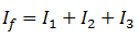
Three voltages V1, V2 and V3 are applied to the inputs and produce currents
I1, I2 and I3.
The inverting input of the OP-Amp is
at virtual ground (0 V) and there is no current to the input.
So, the three input currents I1, I2 and I3 combine at the summing point A and form the
total current If which goes through Rf as shown in fig.1.
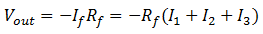
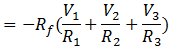
When all the three inputs are applied,
the output voltage is
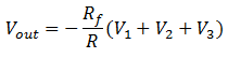
If R1=R2=R3=R, then, we
have,
Thus the output voltage is
proportional to the algebraic sum of the input voltages.
If Rf =R1=R2=R3=R, then, we have
Thus, when the gain of summing
amplifier is unity, the output voltage is the algebraic sum of the input
voltages.
There are
a number of applications of summing amplifiers. Here we will discuss the
following two applications:
1. As
averaging amplifier
For averaging amplifier
R1=R2=R3=R
Rf/R =1/n
where n is number of inputs.
In that case the Vout =
-1/n(V1+V2+V3)
2. As Scaler
amplifier
This condition can be accomplished if Ra, Rb, and Rc are different
in values. Thus the output voltage of the scaling amplifier is :
Vout = - [(RF / Ra) Va + (RF / Rb) Vb + (Rf / Rc)
Vc]
Where RF/Ra ≠ RF/Rb ≠ RF/Rc
OP-AMP AS A VOLTAGE FOLLOWER -
A unity gain buffer amplifier may be constructed by
applying a full series negative feedback (Fig. 2) to an op-amp simply by
connecting its output to its inverting input, and connecting the signal source
to the non-inverting input (Fig. 3). In this configuration, the entire output
voltage (β = 1 in Fig. 2) is placed contrary and in series with the input
voltage. Thus the two voltages are subtracted according to KVL and their
difference is applied to the op-amp differential input. This connection forces
the op-amp to adjust its output voltage simply equal to the input voltage (Vout follows
Vin )so the circuit is named op-amp voltage follower.
Used as a buffer amplifier to eliminate loading
effects (e.g., connecting a device with a high source impedance to a device
with a low input impedance).
The importance of the circuit is due to the input
and output impedances of the op-amp. The input impedance of the op-amp is very
high, meaning that the input of the op-amp does not load down the source or
draw any current from it. Because the output impedance of the op-amp is very low,
it drives the load as if it were a perfect voltage source. Both the connections
to and from the buffer are therefore bridging connections, which reduce power
consumption in the source, distortion from overloading, crosstalk and other
electromagnetic interference.
The voltage follower is often used for the
construction of buffers for logic circuits.
Observations:-
1.
Measure the value of Output
Voltage it should be as per the operation.
2.
The input and output both are the
dc signals.
3.
Observe outputs using different
input voltages and wave type.
Result :-
The op-amp as a scalar, summer and voltage follower
has been studied successfully.
Precautions:-
1.
Connections should be verified
before clicking run button.
2.
The frequency should be in
appropriate range for all voltage used so that the slew rate distortion does
not affect the output.
Comments
Post a Comment